INFLUENCE OF THE CTP IMAGING DRUM SURFACE GEOMETRY ON PRINTS QUALITY
Mahović S.; Agić, D. & Gojo, M.
Abstract: Computer to Plate (CtP) technology has been developed in the last ten years and is today the subject of investigations of a large number of manufacturers. On the graphic product market, there is a considerable number of producers of output CtP devices and printing plates, but their products have not yet been standardized. They offer different platesetter surface geometries for plate imaging, different imaging laser technologies and different active coatings on the printing plates.
In this work, the most represented CtP device architectures of the renowned manufacturers have been investigated and the quality of the plates and prints was compared. The investigations we made are of significance in the field of graphic reproduction because they define the advantages or disadvantages of observed technologies. The analysis of the investigation results was made by measuring the relevant parameters for monitoring the reproduction quality. Results have shown that there were some measurable mechanical and optical differences on the printing plates and prints, but visual assessment of reproduced motives has shown insignificant changes in colour appearance.
Keywords: CtP systems, offset printing, prints quality.
1 INTRODUCTION
The development of electronic hardware and software, data manipulation and the usage of new materials and laser technology has resulted in systems that image directly from computer to printing plates (CtP). Like the majority of the apparently revolutionary inventions CtP technology is the product and result of the investigations in several different fields. Spreading of the usage of the printing plates, laser technology, photopolymer chemistry and DTP influenced the creating of the existing CtP systems [1]. This kind of technology has improved and accelerated printing process, because it eliminates the film making phase from graphic reproduction (Fig. 1). This has enabled achieving more positive economic effect in the context of saving graphic material and chemical substances. From the ecological point of view this technology contributes to maintaining the quality of the environment.

Fig. 1. Conventional (A) and CtP (B) workflow
2 PROBLEM FORMULATION
Three types of platesetter architectures are available: internal and external drum geometry and flat bed geometry. The choice of these geometries can significantly aff ect the quality of the image output [2]. Other aspects of imaging surface geometry also affect the image quality: writing beam configuration, beam positioning system, vacuum hold down system and material docking system. If there are any variationsin any of these aspects the changes in printing plates and prints quality may occur. Nowadays, the prevalent geometries of the CtP device in graphic reproduction are internal and external drum.
The aim of this paper was the comparison of the quality of the printing elements on the printing plates and screening elements on the prints with the internal and external drum imaging system workflow.
2.1 Axis assignments
Internal drum, external drum and flat bed surface geometry make use of three axes of motion to create an image: X, Y and Z [3] . The X axis is arbitrary assigned to the “slow scan axis”, the Y axis is assigned to the “fast scan axis” and the Z axis represents the modulation of the data (on/off information) (Fig. 2)
Fig. 2. X, Y and Z axis
Two critical components of internal and external drum system that affect the image quality are runout and cylindricity [2] . Runout is the measure of positional error relative to a defined center of axis motion and causes drum wobbling. Cylindricity is a measure for roundness and is the problem in which all points on the surface are equidistant from common axis. Wobbling of the drum and variations in cylindricity change the writing beam depth of focus and creates artifacts on the printing plates.
2.2 Internal drum surface geometry
CtP device with internal drum geometry has stationary printing plate which is placed in a cylindrical trough [3]. The rotating mirror is located precisely in the geometrical axis of the drum (Fig. 3). During the imaging, writing beam is reflected from the mirror and hits the optics with the rotating mirror which deflected the beam onto the printing plate surface. The writing beam moves over the material surface in the fast scan axis and in the same time moves down the slow scan axis and forms an image. As a result of rotating process, mechanical runout and cylindricity errors are possible. Even a very small error will be visible on the plates and consequentially on the prints.
Fig. 3. Internal drum surface geometry
2.3 External drum surface geometry
In the CtP device with external drum geometry, plate is mounted on a drum, on the same principle as with the plate cylinder of a printing process (Fig. 4). The slow scan axis is located outside the drum and the plate rotates with the drum in the fast scan axis. Optical head with multiple writing beams moves in the slow scan axis of motion.
Fig. 4. External drum surface geometry
The crucial advantage of the external drum imaging geometry over the internal drum is that both structurally and optically it is relatively easy to focus several laser beams on the plate surface simultaneously. This leads to a corresponding reduction in imaging time for the entire plate. During the imaging, external drum wobbles slightly due to runout as it rotates which can cause focus errors. Focus problems could be also caused by higher speeds when plate can throw the drum out of balance.
3 EXPERIMENTAL
Computer generated original has been reproduced by the computer led CtP systems directly onto the thermal printing plates [4] and has been printed out in offset. Original consisted of the control wedge for instrumental measurement and characteristic motives for visual assessment.
The measurings were performed on the tone patches of the primary colours of the subtractive synthesis (cyan, magenta, yellow and black). Device with the CCD camera for measuring the mechanical deformations of the printing and screen elements and densitometer for measuring the optical deformations of screen elements have been used. Before the experiment the CtP systems characterization was made. T he printing process has been led in controlled conditions concerning ink and fountain solution, and the printing substrate has not been changed.
4 RESULTS AND DISCUSSION
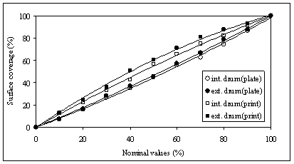
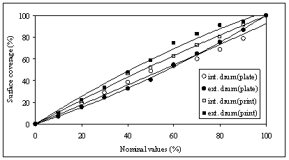
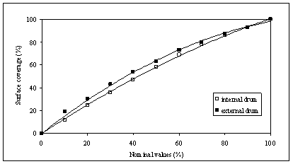
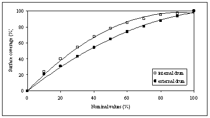
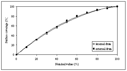
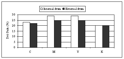
Mechanical characteristic of the printing elements on the printing plates and screening elements on the prints were measured with device with the CCD camera. Results point at relatively uniform values (Fig. 5, 6, 7, 8). For cyan, magenta, yellow and black mechanical characteristics of the surface coverage on the plates and on the prints were similar.
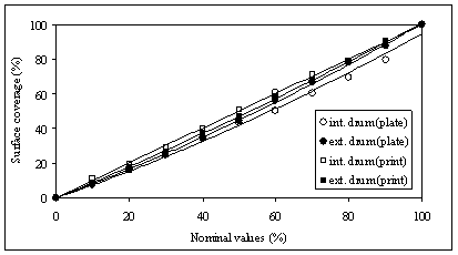
Fig. 5. Surface coverage on the printing plates and prints (cyan)
These results were expected because they resulted from adequate and frequent platesetter and printing machine characterisation. Platesetter characterisation include: laser power controlling, focus, zoom and rotation speed adjustment which is indispensable for optimal reproduction [5] . Two CtP systems used in this research as well as the print machine have been regularly maintained according to the types of printing plates, paper and inks used in production.
