Behaviour of some custom programmed screening elements in various printing systems
Ziljak I, Pap K, Agic D.
Faculty of Graphic Arts, Zagreb, Croatia
Email: ivana.ziljak@zg.t-com.hr
klaudio.pap@zg.t-com.hr
darkoagic@yahoo.com
Abstract:
Most commercial graphic arts reproduction systems use screening or printing elements for coverage and-or applying the inks to the substrate. In that way the specific reflectance of some area is changed, so various shades of gray or in the separation principle various shades of color are obtained. Standard screening systems combine adequate rulings with screening elements that are usually round, square, various eliptical shapes, in some specific situations lines waves or special technical shapes are used (1). They are usually presented as modules in RIP system. Todays purposes are more wide, and some specific or custom designed elements can be programmed and applied in various fields of use. According to their shape, their usage has to be considered with more care, because not only reproduction, but also the specific message could be poor.
Keywords: individualisation screening elements, PS programming, coverage, dot gain, linearisation curves
1. Theoretical part
Postscript programming opened the way for describing various shapes, curves, as well various objects that can be mathematically described. In this work seven various shapes are developed in correlation to the “standard” shape, the round one (picture 1). All of them were programmed to fulfill the continous range of coverage from non-covered area to the solid tone.

R1 R2 R3 R4 R5 R6 R7 R8
Fig 1: programmed shapes of screening elements, labeled as R1-R8 , at 0,5 coverage
For the purpose of examinations they were reproduced as a standard offset Matchprint proof , and printers copies on the semicoated (les absorbing substrate K1), and rather absorbing printing substrate K2. Scanned picture if reproduction is showed on fig 2:
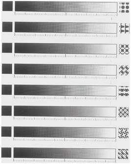
Fig 2: scanned printed sheet
It is evident from the fig. 2 that that the reproduction with such custom designed elements is possible, but we must differ them from the "standard" reproduction using round, square elliptical or some specific technical shape inserted as a module in the RIP system. PS programming (2) allows us to define or construct any possible shape, element or object mathematically described as curves. It is allowed their use in usual way, but their usage correspond to apply them also in various artistic purposes, they can carry a special message, change their size, they can incorporated in security documents and personalisation (3). It can be also seen from fig.2 that the density distribution and density range differ in given examples. From some prior examinations it was decided that ruling in that situation over 20 lin-cm has no sense. It depends of course on the complexity of the element and the quality of the reproduction system used.
An example for the programmed element and its imposition in the chart is given as following:
/r4 Wheat Ear
/r5 Hanger
/polje [{r4} {r5} ] def
/L 7 def %linijatura
/K 45 def %kut
/polumjer 50 def
/siva 0.9 def
gsave
250 300 translate
/j 0 def
7 {
siva 0.1 sub
/siva exch def
siva setgray
0 0 moveto
0 0 polumjer 0 360 7 div arc
0 0 lineto
50 10 add
/polumjer exch def
closepath 7 45 polje j get bind setscreen fill
360 7 div rotate
/j j 1 add def
j 1 gt {/j 0 def} if
} repeat
grestore
showpage
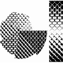
Fig.3: example of programmed element and its applying to the chart
2. Experimental
To get some information for reproduced elements dot gain values were determined in reference to film round element coverage (Table 1. for Matchprint, table 2. for paper quality 1, table 3. for paper quality 2)
film |
Matchprint |
coverage |
|
|
|
cover. |
|
|
|
|
|
|
|
|
|
M R1 |
M R2 |
M R3 |
M R4 |
M R5 |
M R6 |
M R7 |
M R8 |
10 |
11 |
19 |
22 |
19 |
14 |
32 |
22 |
26 |
20 |
24 |
27 |
34 |
45 |
29 |
44 |
34 |
35 |
30 |
36 |
42 |
43 |
54 |
42 |
53 |
45 |
46 |
40 |
48 |
50 |
54 |
61 |
57 |
59 |
54 |
61 |
50 |
59 |
61 |
62 |
65 |
61 |
67 |
63 |
68 |
60 |
66 |
66 |
70 |
73 |
70 |
73 |
69 |
74 |
70 |
78 |
74 |
78 |
79 |
79 |
79 |
77 |
80 |
80 |
85 |
83 |
86 |
88 |
87 |
87 |
86 |
87 |
90 |
92 |
92 |
94 |
96 |
94 |
96 |
93 |
95 |
Table 1: coverage of Matchprint printed elements vs film coverage
film |
|
paper T1 coverage |
|
|
|
coverage |
T1 R1 |
T1 R2 |
T1 R3 |
T1 R4 |
T1 R5 |
T1 R6 |
T1 R7 |
T1 R8 |
10 |
29 |
32 |
34 |
34 |
36 |
36 |
27 |
36 |
20 |
47 |
53 |
61 |
62 |
62 |
58 |
59 |
49 |
30 |
64 |
67 |
76 |
70 |
65 |
72 |
72 |
72 |
40 |
73 |
77 |
84 |
81 |
74 |
83 |
82 |
82 |
50 |
83 |
84 |
91 |
86 |
83 |
89 |
87 |
91 |
60 |
89 |
89 |
94 |
92 |
92 |
93 |
93 |
93 |
70 |
93 |
93 |
97 |
96 |
95 |
97 |
95 |
97 |
80 |
95 |
97 |
98 |
99 |
97 |
98 |
98 |
99 |
90 |
98 |
99 |
99 |
100 |
100 |
100 |
100 |
100 |
Table 2: coverage on T1 paper quality vs film coverage (Dsolid 1,48)
film |
|
paper T2 coverage |
|
|
|
|
coverage |
T2 R1 |
T2 R2 |
T2 R3 |
T2 R4 |
T2 R5 |
T2 R6 |
T2R7 |
T2 R8 |
10 |
27 |
27 |
28 |
32 |
38 |
32 |
26 |
32 |
20 |
45 |
46 |
52 |
50 |
48 |
51 |
53 |
50 |
30 |
60 |
66 |
67 |
71 |
67 |
69 |
71 |
69 |
40 |
72 |
75 |
80 |
78 |
71 |
81 |
84 |
77 |
50 |
80 |
82 |
88 |
83 |
81 |
87 |
87 |
88 |
60 |
88 |
89 |
93 |
90 |
87 |
93 |
93 |
92 |
70 |
92 |
92 |
96 |
93 |
93 |
97 |
95 |
95 |
80 |
95 |
97 |
98 |
98 |
96 |
98 |
96 |
98 |
90 |
99 |
99 |
99 |
100 |
99 |
100 |
99 |
100 |
Table 3: coverage on T2 paper quality vs film coverage (Dsolid 1.37)
According to tables, elements build their specific reproduction shapes, a term corresponding to reproduction curves. The round element has an optimal shape with lower dot gain, but elements R4 and R8 are more complex with a higher dot gain. It appears that the gain curve is not sufficient for estimating the reproduction of an element. Its specific shape, “free edge”, or complexity would be very important not the only responsible factor for achieving the range of reproduction of tones, although the whole imaging system corresponds.
An optical estimation has to be done to determine useful beginning of the reproduction, and the place pretending to the solid tone with the loss of basic characteristic of elements. This could be determined as an basic density range. On film and Matchprint reproduction all elements reproductions are approximately more accurate with a rather longer density range, but on paper imaging (eg for R8) the reproduction is considerably lower and useful density range is lower, so the first useful element appears eg at 20 percent coverage, or more, and ends at approximately 60 percent of useful coverage. Presented pictures are 14 times enlarged.
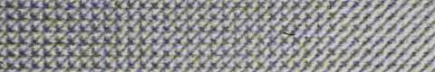
Fig 4: For element R8 areas from 20 to 10 % coverage (T1)
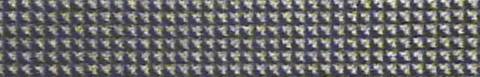
Fig 5: For element R8 50 % coverage (T1)
Fig 5: For element R8 areas from 60 to 70 % coverage (T1)
From figures 4 , 5 and 6 is obvious that the useful range of reproduction has to be carefully chosen for the reproduction system used for each element. If not, such custom designed element will lose their specific information or message, and the whole reproduction becomes out of sense.
3. Conclusion
Custom designed screening elements are rather new area of interest provided by PS programming. Their usage and application can vary wide from standard reproduction to very specific artworks, effects and design. Applying appropriate shape of element to nonadequate magnification, color, relief , substrate or any possible magnitude, unexpected and unpredictable effects can occur. Of course knowledge about matherials, colorants, technology is necessary, but also knowledge about behaviour of programmed elements in various situations, its possible range, the point of maximum gain, the point of useful appearance and ending an other imaging characteristics im reproduction process.
4. Literature
1. Morgenstern D.: Rasterung technik, Polygraph Verlag 1985, Frankfurt
2. V. Žiljak, K. Pap: "PostScript, programiranje grafike", FS d.o.o., Zagreb, 1998, ISBN: 953-199-000 3. J. Žiljak, V. Vančina, D. Agić, I. Žiljak, K.Pap:"New screening elements in multi-colour printing for special purposes ", 30th International Research Conference of IARIGAI, Dubrovnik, 2003,
ISBN 953-96276-6-4