Abstract :
The usage of the silver halide technology in the graphic reproduction is not a novelty. The filmmaking phase is based on the usage of the silver halide as the photographically active ingredient, for instance, AgBr (silver bromide). The new, digital plate making technology (Computer to Plate, CTP) eliminates the filmmaking phase and therefore enables the plate making directly by the computer1. The photosensitivity of the silver halide has been used in the Computer to Plate technology as well. The photosensitive copying layer is no long based on diazo type components2, which was the case in the conventional plate making systems, today; it is made of silver halide. Not only has the CTP technology eliminated the filmmaking phase, but it has also resulted with the reduction of the quantity of the materials used and required time for the production3, 4.
In this paper the basis of the graphic reproduction by using the silver halide digital printing plates was described. The changes of the AgX copying layer and the surface of the aluminium base in the printing process have been observed. The surface characteristics were determined by measuring the relevant surface roughness parameters. This also provided insight into the influence of these changes on the quality of the prints. Such measurings are of great value in the graphic reproduction. They enable us to determine the consistency of the printing plates during the printing process, to predict the endurance as well as to define the print run which will result with optimal quality prints.
1 Introduction
Conventional reproduction system (analogue reproduction) is characterized by the use of film, camera, copy technology, and photomechanical (hardened or softened by light) emulsions, as well as mechanical and chemical processes for producing the printing plates. The materials and equipment used for analogue reproduction have reached a stage of development that allows them to satisfy very high quality demands in printing plate production and process safety. During platemaking itself, the master copy (film) is transferred optically onto the light-sensitive layer of the printing plate. A printing plate is produced for each primary colour (cyan, magenta, yellow, black, CMYK) of the intended print on the basis of the corresponding colour separation5, 6. With a contact exposure, the developed film layer emulsion lies on top of the light-sensitive layer of the unexposed printing plate. Exposure of the unexposed printing plate in accordance with the image is followed by developing process using the chemical/physical processes appropriate to its material. This is followed by the final treatment of the plate, in which the latter undergoes after-treatment and is prepared for fitting in the press7. The printing process consists of following processes: application of damping solution, application of the printing ink and production of reproduction (Fig. 1).
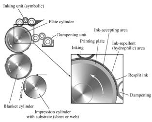
Figure 1. Offset printing8
The printing plate which consists of texts and illustrations is covered first by the damping solution by means of the damping roller system. The damping solution is absorbed into the nonprinting areas preventing the later possible adsorption of the printing ink into the same area. By turning the plate cylinder, the printing plate comes on the inking system and transfers the ink on the printing elements on which the damping solution did not adhere. From the printing plate
(plate cylinder) the paste ink and the damping solution are transferred on the offset cylinder covered by the rubber blanket which is placed between the plate and impression cylinder, and the printing substrate (most often paper) passes between the offset and impression cylinder. The offset cylinder has the role of the ink transfer between the printing plate and the printing substrate and we speak about the indirect printing technique. Because of that the printing plate is laterally reversed. Great advantage of such printing technique is the adaptation of the rubber blanket to different substrates. In this way the determined printing quality level even on a bad paper can be maintained. The role of the impression cylinder is to realize the corresponding pressure and to transport the printing substrate. To enable this process, the printing and nonprinting areas (on the printing plate) must differ in their physical-chemical characteristics. Water adheres to the nonprinting areas and ink to the printing areas. The technique is based on selective damping of the nonprinting areas by the fountain solution. The printing elements and the nonprinting areas are on the same level, i.e. they have negligible geometrical difference. It is several micrometers. The nonprinting areas are hydrophilic, they attract water, i.e. they are oleophobic because they reject ink while the printing areas are oleophilic. i.e. hydrophobic because they absorb the ink, based on oil. Their hydrophobic ability is not so much expressed and this is the reason why it is necessary to apply the fountain solution first so that it can cover the nonprinting areas and prevent the toning. Consequently, in production of the printing plate it is essential to obtain the necessary physical-chemical characteristics of the printing and nonprinting areas.
2 Printing Plate Production
Aluminium is the material most used in plate making production. It is mostly 0,3 mm thick and its surface is coated with a thin photo-sensitive layer. During the plate production the surface of the aluminium is made rough. The necessary graining of the aluminium surface is done in an electrolytic process (anodizing), that is, electrochemical graining with subsequent oxidation. This roughness of the aluminium surface is necessary for a number of reasons. The most important one is that it enlarges the contact area what causes better ink adhesion. Nevertheless, the surface should not be to rough because it might result with the reduction of
sharpness of the screening element on the paper surface, which in turn might cause the decrease of the reproduction quality. Through the printing plate exposure, the silver halide coating is decomposed photo chemically and by developing process the exposed light-sensitive areas are removed from the base (aluminium). The thin coating of aluminium oxide has a particularly stable water-attracting (hydrophilic) surface with special retention properties. Other parts of the surface, with the silver components will, due to its hydrophobic quality accept the printing ink (Fig. 2). Both, the printing element surface (silver) and the nonprinting element (aluminium-oxide) surface are being worn through the printing process. This is the reason why a decrease of the ink transfer occurs, which in turn reduces the percentage of the coverage on the paper. The changes of the printing plate surface occur after a certain number of prints and therefore influence their quality9. The standardization of the printing process becomes simpler by predicting the possible changes of the prints and by following the parameters which could have influence on their quality. These steps bring certain advantages to the printing houses in the sense of reduction of the reproduction time, as well as the planning of the financial dimension.
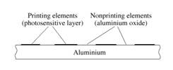
Figure 2. Characteristics of the offset printing plate
3 Experimental Details
The wearing of the printing plate surface can indirectly be investigated by measuring the percentage of the coverage of the printing elements on the printing plate and on the prints10, and directly, by measuring the changes of the roughness parameters on the printing and nonprinting areas on the printing plate11. In this paper the basis parameters for reproduction quality and the consistency of the silver layer during printing process were investigated. Consistency of the silver layer was measured through defining the roughness parameters of the printing plate surface. Roughness parameters have significant role in the printing process because they define the consistency of the copying layer and, upon this, the consistency of
the printing plates. The characteristics of the printing plate surface (roughness parameters for silver and aluminium-oxide areas) before the print run and possible changes of the roughness after the print run were investigated. Also, the possible changes of the printing elements coverage on the printing plates during the printing process and their possible influence on the prints were measured. Investigation of the roughness characteristics of the printing plate surface was performed by electronical-mechanical equipment with the stylus Perthometer. For measuring the mechanical characteristics of the coverage on the printing plates and prints the device with the CCD camera has been used. Measured parameters have significant importance in the graphic inking repro-duction process. Results of this paper have shown in which amount the wearing of the printing plate surface and silver areas influence on print quality.
4 Measurement
The surface roughness is a very complex and its estimation demands necessary simplification. It is revealed through the quantification system of surface roughness condition by one-dimensional parameters based on shot of two-dimen-sional profile on the part of the investigated surface. In regard to the amplitude and the horizontal characteristics of the profile, there are horizontal surface parameters, vertical ones and hybrid ones. The modern equipment for measuring the surface roughness enables measurements of great numbers of parameters, each describing a single charac-teristic of the surface roughness12. The choice of the rough-ness parameters which will give the optimal characteristics of the surface depends firstly on the process of its elaboration and the function of investigated surface.
The investigated roughness parameters are defined according to the ISO/DIS 13565-2 (1994) standard on the curve of relative length carrying capacity, so called Abbott’s curve13,14. Abbott’s curve gives the relative share of the material as a function of the line high cross section and describes relative growth of the material share with the increasing profile.
In this paper, the printing plate surface was evaluated through following amplitude parameters:
Rz – mean peak-valley height in 10 dots. It describes the differences between middle height
of the five highest peaks and the five lowest valleys inside the reference length.
Ra – arithmetical mean of the roughness, (roughness average)
Rp – the highest peak inside the reference length;
and through following hybrid parameters:
Rk – core roughness depth, working surface which will influence the consistency of the material (printing plate)
Rpk – reduced peak height, main part of the surface which will be worn out through the processing (printing process)
Rvk – reduced valley depth.
The surface characteristics were also measured indirectly, by measuring the surface coverage of the printing elements on the printing plates and surface coverage of the screening elements on the prints. The measurements were made by device containing the CCD camera for defining the mechanical characteristics of the coverage.
5 Results and Discussion
The investigation was made on printing plates with AgX coating before print run (in the results market with “0”), after 1000 prints (marked with “1000”) and after 350000 prints (marked with “350000”). The surface roughness was measured on the silver coating (marked with “Ag”) and on the aluminium-oxide surface (marked with “Al”). All the measurements were performed in the same measurements conditions using Gaus filter of limited wave length λB=0,8 mm with the evaluation length ln=0,4 mm and standard stylus RHT 6-50. For more accurate results each printing plate sample has been measured on five places in parallel printing direction. In the figures 3 and 4 the middle values of the performed measurements are shown.
Figure 3. Results of measurements of Rz, Ra, Rp
surface roughness parameters
Figure 4. Results of measurements of Rk, Rpk, Rvk
surface roughness parameters
The results of the measurement show that there is a certain reduction of all measured parameters after the print run of 350000 prints. By measuring the amplitude parameters Rz, Ra, Rp it can be seen that there is an increase of 0.1 to 0.3 mm on the Ag surface (ink carrier) after 1000 prints. This is most likely the consequence of the residual paper particles (which are transferred from offset cylinder on the printing plate) and ink particles on the ink carrier surface. During the printing process these small particles are placed in the profile valley depth. After the print run of 350000 prints the roughness of the surface decreases. The roughness parameters are also smaller due to mechanical wearing of the printing plate surface. That is to say, during the printing process, in the touching zone between the offset cylinder and the plate cylinder the rubber web slightly slides on the offset cylinder, and therefore causes abrasive damaging of both nonprinting (aluminium-oxide) and printing (Ag) surfaces15. The reduction of the surface roughness will directly cause the reduction of the ink transfer from the printing plate onto paper. This will in turn result with prints of poorer quality. By observing these elements on the used printing plates one can notice the disappearance of the smallest printing elements which are important for the appearance of the light tones on the prints.
Measurements of the hybrid roughness parameters Rk, Rpk, Rvk have shown that there is a reduction both on the Ag surface and on the aluminium-oxide surface. The results are shown in fig. 4). The reduction of the Rk parameter points at the reduction of the roughness core depth. The reduction of the Rpk parameter signifies the smoothing of the surface, and the decrease of the Rvk parameter points at the reduction of the deeper tracks. These results are confirmed by the comparative presentation of the diagrams, as shown in the fig. 5.
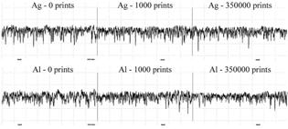
Figure 5. Comparative presentation of the diagrams
of the tested profiles
The results shown in the fig. 6 have been obtained by the indirect measuring of the surface coverage at 40% of coverage (middle tones).
Figure 6. Results of the 40% of the coverage
of the printing plates and prints
It can be seen that after the print run there is a noticeable decrease of the coverage percentage on the printing plates as well as on the prints. It is assumed that the reduction of the ink transfer on the paper come as a result of wearing of the copying layer on the printing surfaces, that is as a result of the reduction of the printing plates surface roughness. On parts of the printing surfaces which contain copying layer (Ag) an aluminium surface arises after the long print run. Such surface will not accept ink and transfer it to the paper due to its characteristics which are different than those of the copying layer. Because of that there is a reduction of ink transfer and the reduction of the surface coverage of the prints.
6 Conclusion
By observing the amplitude and the hybrid roughness parameters it can be seen that the roughness of the surface on the printing plates decreases during the printing process. The defining of the mentioned roughness parameters are important both to the printing plate’s
manufacturers and to their final users (print houses). The observing of only one of the stated parameters (for example Ra - arithmetical mean of the roughness or Rpk - reduced peak height, main part of the surface which will be worn out through the printing process) is not the adequate approach to defining the printing plates consistency because the evaluated changes after the print run of the 350000 prints are relatively small. Therefore more complex approach to defining the roughness and some similar parameters is recommendable, as well as a detailed analysis of the changes in the Ag layer through the printing process.
7 Literature
1. Adams Richard M., Romano F.,
Computer to Plate: Automating the Printing Industry, Graphic Arts Technical
2. Richter S., Lichtempfindliche Diasoschichten auf Offsetplatten, Fachhefte Bulletintechnique 4, 178-186 (1978).
3. Limburg M., Der Digitale Gutenberg – Alles was Sie über “Computer to Plate” wissen sollten, GSS-Grafik System Service, Aachen, 1994.
4. Seydel M., Computer to Plate: Digital Workflow and Integration into Quality Offset Printing, TAGA Proceedings, Rochester (NY), 634. (1996).
5. Ihme R., Lerhbuch der Reproduktionstechnik, VEB Fachbuchverlag, Leipzig, 1982, 30-39.
6. Southworth M. F., Color Separation Techniques, Graphic Arts Publishing-2nd Edition, Livonia, N.Y., 1979, 194-226.
7. Walenski W., Einführung in der Offsetdruck, Hanns Eggen GmbH&Co KG, Hannover, 1975, 215-216.
8. Kipphan H., Handbook of Print Media, Springer, Berlin, 2001, 503-626.
9. Mahovic S., Agic D., Gojo M., Mechanical and Optical Differences in Long Run Printing in Conventional and CtP Offset Systems, Proceedings of the 30th International Iarigai Research Conference, Croatia, 219. (2003).
10. Bosner Z., Ferencek B., Korelic O., Trosenje ofsetne tiskovne forme u toku tiska, Acta Graphica 1-1, 43 (1989).
11. Bosner Z., Korelic O., Kunst M., Određivanje istrosenosti ofsetnih tiskovnih povrsina mjerenjem impedancije, Acta Graphica 3-1, 1 (1991).
12. Mahovic S., Marosevic G., Surface Roughness of the Offset Rubber Blanket, Acta Graphica 9-1, 1 (1997).
13. Drevs P., Weniger R., Redisovering the Abbott-Firestone Curve-Quality, 15-3, 1989, 50-53.
14. ISO/DIS 13565 1, 2, 3 (1994), Characterisation of Surfaces Having Stratified Functional Properties.
15. Bauer G., Marosevic G., Tribosystem of the Letterpress, Zbornik radova Intergrafika 1987, Croatia, 247. (1987).